In many cases of structural and machine designs, members must resist the force applied laterally or transversely to their axes. Such members are called beam. The main members supporting floors of buildings are beams, just as an axle of a car is a beam. Many shafts act simultaneously as torsion members and as beams. So far it can be said beam is an integral part of the construction.
Beam Deflection
Beam deflection means the state of deformation of a beam from its original shape under the work of a force or load or weight. One of the most important applications of beam deflection is to obtain equations with which we can determine the accurate values of beam deflections in many practical cases. Deflections are also used in the analysis of statically indeterminate beams.
Methods to Determine Beam Deflection
Several methods are available for determining beam deflections. The principle is the same but differs in technique and in their immediate objective.
- Direct Integration Method
- Area moment Method
- Conjugate Beam Method
- Method of Superposition
Direct Integration Method
Beam deflections due to bending are determined from deformation taking place along a span. This is based on the hypothesis that during bending, plane sections through a beam remains plain. For now, it will be assumed that bending takes place only about one of the principal axes of the cross-section. The edge view of the neutral surface of a deflected beam is called the elastic curve of the beam. The differential equation of the elastic curve of a beam:
The product EI is called flexural rigidity of the beam which is usually constant along the beam.
v = deflections of the elastic curve
θ = dv/dx = v' = slope of the elastic curve
By simplifying-
Here q(x) is the load function. The choices of which equation we will use to determine v depends on the ease with which an expression for moment, shear or load can be formulated.
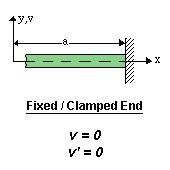
Some Boundary Conditions:
- Clamped or fixed support:
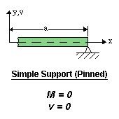
- Roller or pinned support:
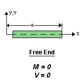
In this case. the end is free to rotate, that’s why the moment is zero. - Free end:
- Guided Support: