Foundation is one of the most important parts of the structure. Foundation is defined as that part of the structure that transfers the load from the structure as well as its own weight over a large area of soil in such a way that the load does not exceed the ultimate bearing capacity of the soil and the settlement of the total structure remains within a tolerable limit.
Pile foundation, a kind of deep foundation, is actually a slender column or long cylinder made of materials such as concrete or steel which are used to support the structure and transfer the load at desired depth either by end bearing or skin friction.
Friction Pile
Friction pile is a kind of pile foundation. This type of pile utilizes the frictional resistance force between the pile surface and adjacent soil to transfer the superstructure load. Depending on the subsoil strata condition, resistance force due to friction can develop in a definite pile length of on the full length. For a stable foundation condition, the friction force must be adequate to support the superstructure.
How to Calculate Friction Pile Capacity?
To calculate the capacity of a friction pile one has to multiply the pile surface area to the safe friction force developed per unit area.
The skin friction to be developed at a pile surface should be evaluated sincerely and a reasonable factor of safety should be considered.
How to Increase Friction Pile Capacity?
To increase the friction pile capacity pile diameter, depth, pile number, and pile surface roughness, etc. can be increased.
Pile foundations are essential elements in civil engineering, providing support to structures in various soil conditions. These foundations utilize vertical columns known as piles to transfer loads from superstructures to deeper layers of soil or rock. In this article, we'll explore the advantages and disadvantages of using pile foundations for construction projects.
Advantages of Pile Foundations
The followings are the pile foundation advantages:
Load-Bearing Capacity: Pile foundations offer high load-bearing capacity, making them suitable for structures subjected to heavy loads and challenging soil conditions.
Versatility: Pile foundations can be adapted to different types of soil, including cohesive, non-cohesive, and mixed soils, allowing for flexibility in construction projects.
Settlement Control: Pile foundations can effectively control settlement, ensuring that the structure remains stable and levels are maintained over time.
Limited Space Requirements: Pile foundations require less horizontal space compared to other types of foundations, making them ideal for constrained construction sites.
Deep Foundation Solution: Pile foundations are particularly useful in areas with weak or unstable upper soil layers, as they can reach deeper, more stable soil or rock layers.
Mitigation of Lateral Forces: Pile foundations provide resistance against lateral forces such as wind or earthquakes, enhancing the structural stability of the building.
Durability: Pile foundations are designed to resist corrosion and deterioration, ensuring the long-term stability and safety of the structure.
Suitable for Various Structures: Pile foundations are used for various types of structures, including buildings, bridges, piers, and retaining walls.
{adselite}
Disadvantages of Pile Foundations
The followings are the pile foundation disadvantages:
Cost: Pile foundations can be more expensive compared to shallow foundations due to the materials, equipment, and specialized labor required for their installation.
Complex Design and Installation: Designing and installing pile foundations require expertise and engineering knowledge, which can add complexity to the construction process.
Noise and Vibration: Pile installation can generate noise and vibrations, potentially causing disturbances to nearby structures and the surrounding environment.
Environmental Impact: Pile installation may impact the local environment, including noise pollution, soil displacement, and disruption to aquatic habitats.
Limited Accessibility: Pile foundations may not be suitable for sites with limited access to installation equipment.
Maintenance Challenges: While pile foundations are durable, maintenance and repairs may be more complex compared to shallow foundations.
Potential for Pile Failure: If not designed and installed correctly, piles can experience failure due to factors such as inadequate load capacity or poor soil conditions.
Pile foundations offer a range of advantages, including high load-bearing capacity, settlement control, and versatility in challenging soil conditions. However, they also come with disadvantages, including higher costs, complex design and installation processes, and potential environmental impacts. Ultimately, the decision to use pile foundations should be based on the specific requirements of the construction project, considering factors such as soil conditions, structural loads, budget, and environmental considerations.
Before the engineer can design a foundation intelligently, he must have a reasonably accurate conception of the physical properties and arrangement of the underlying materials. The field and laboratory investigations required to obtain this essential information are called soil exploration or site investigation.
A site investigation simply is the process of the collection of information, the appraisal of data, assessment, and reporting without which the hazards in the ground beneath the site cannot be known.
Site investigation is carried out in order to enable a geotechnical and geoenvironmental assessment of the ground conditions and analysis of the engineering and environmental considerations related to the proposed development.
Purpose and Objectives of Site Investigation
In A Client's Guide to Site Investigation, the AGS states that adequate site investigation is of importance to the civil engineer for the successful completion of any building project,
The design of a structure which is economical and safe to construct, is durable and has low maintenance costs, depends upon an adequate understanding of the nature of the ground. This understanding comes from an appreciation of the distribution of the materials in the ground, and their properties and behaviour under various influences and constraints during the construction and lifetime of the structure. An adequate and properly structured site investigation is therefore an essential part of any civil engineering or building project.
{adselite} The primary objective of a site investigation is to determine as accurately as may be required-
The nature and sequence of strata;
The ground water conditions at the site;
The physical properties of soil and rock underlying the site;
The mechanical properties, such as strength and compressibility of different soil or rock strata, and
Other specific information, when needed, such as the chemical composition of the groundwater, and the characteristics of foundations of the adjacent structure.
Site investigation should be organized to obtain all possible information toward a thorough understanding of the subsurface condition and probably foundation behavior.
Background Information before Subsurface Investigation
Before actual field investigation is started, the information should, whenever possible, be collected on:
The type of structure to be built, its intended use;
Characteristics of the structure;
Starting date;
Intended construction method;
The estimated period of construction;
The probable soil condition at the site, by geological, geotechnical or aerial analysis;
The behavior of existing structures adjacent to the site, as well as other facts available through local experience.
The Extent of Soil Investigation
Subsurface condition at a site may be relatively uniform or extremely variable and will largely determine the complexity of the problems to be faced in both design and construction of the foundations. The subsurface investigation must, therefore, be of sufficient extent to provide enough information for a thorough understanding of the interaction of proposed foundations and supporting soil or rock on which to base a safe and economical design.
Depth of Site Investigation
The site investigation should be carried to such a depth that the entire zone of soil or rock affected by the changes caused by the building or the construction will be adequately explored. This may be taken as depth at which vertical stress induced by the new construction is smaller than 10% of the existing overburden stress at that level.
Where the depth of investigation cannot be related to background information, the following guidelines are suggested.
It is good to have at least one boring carried to bedrock, or to well below the anticipated level of influence of the building.
For light structures, insensitive to the settlement, the boring should be to a depth equal to four times the probable footing width or to a depth of 6m below the lowest part of the foundation, whichever is deeper.
For more heavily loaded structures, such as multistory structures and for framed structures, at least 50% of the borings should be extended to a depth equal to 1.5 times the width of the building below the lowest part of the foundation, and
Bedrock should be proved by coring into it to a minimum depth of 3m.
Stages of Site Investigation
The approach adopted for a particular site investigation, its extent and the techniques used will all depend upon the site-specific circumstances, and the experience and judgment of those involved. There is no single way to carry out an investigation, and inevitably different advisors will adopt different approaches for any particular project. However, it is usual for the site investigation to be a phased exercise.
For any project soil investigation is usually performed in several stages, i.e., during feasibility and planning stage, before construction and during construction (if required). These are termed as:
This phase includes gathering information such as the type of structure to be constructed and its future use, the requirements of local building codes, and the column and load bearing wall loads.
Considerable savings in the exploration program can sometimes be realized if the geotechnical engineer in charge of the project thoroughly reviews the existing information regarding the subsoil conditions at the site under consideration. Useful information can be obtained from the following sources.
Existing soil exploration reports prepared for the construction of nearby structures.
The engineer should visually inspect the site and the surrounding area. In many cases, the information gathered from such a trip is invaluable for future planning. The type of vegetation at a site may in some instances the type of subsoil that will be encountered. Open cuts near the site provide an indication about the subsoil stratification. Cracks in the existing wall of nearby structures may indicate settlement from the possible existence of soft clay layers or the presence of expansive clay soils.
Detailed Site Investigation
This phase consists of making several test borings at the site and collecting disturbed and undisturbed soil samples from various depths for visual observation and for laboratory tests. No hard and first rule exists for determining the number of borings or the depth to which the test boring is to be advanced. For most buildings, at least one boring at each corner and one at the center should provide a start. Depending on the uniformity of the subsoil, additional test borings may be made. The test borings should extend through unsuitable foundation materials to firm soil layers.
Supplementary Investigation and Construction Control
The following supplementary investigation is made to give a full picture of the site investigation of soil as well as the structure.
Any special features such as the possibility of each quake or climatic factors such as flooding, seasonal swelling, and shrinkage, permafrost, or soil erosion.
The availability and quality of local constructional materials such as concrete aggregates, building and road stone, and water for constructional purposes.
For maritime or river structures information on normal spring and neap tide ranges, extreme high and low tidal ranges and river levels, seasonal river levels and discharges, the velocity of the tidal and river currents and other hydrographic and meteorological data.
Results of laboratory tests on soil and rock samples appropriate to the particular foundation design or construction problems.
Results of chemical analysis of soil, fill materials, and groundwater to determine possible deleterious effects on foundation structures.
Results of chemical and bacteriological analysis of contaminated soils, fill materials and emissions to determine health hazard risks.
what is site investigation in construction, objectives of site investigation, site investigation in construction, site investigation in building construction, purpose of site investigation in construction
For designing shallow foundations, it is necessary to know the bearing capacity of soil at the desired depth. The plate load test is performed on-site to determine the ultimate bearing capacity of soil at the desired depth. Data from the plate load test is helpful to confirm the design assumptions made from soil tests or can be used as a design parameter.
The plate load test is a field test, which is performed to determine the ultimate bearing capacity of the soil and the probable settlement under a given load. This test is very popular for the selection and design of the shallow foundation.
For performing this test, the plate is placed at the desired depth, then the load is applied gradually and the settlement for each increment of the load is recorded. At one point a settlement occurs at a rapid rate, the total load up to that point is calculated and divided by the area of the plate to determine the ultimate bearing capacity of soil at that depth. The ultimate bearing capacity is then divided by a safety factor (typically 2.5~3) to determine the safe bearing capacity.
Plate Load Test Apparatus / Equipment
The following plate load test apparatus is necessary for performing the test.
A steel plate is at least 300 mm square and 6 mm thick.
Hydraulic jack & pump
A hydraulic jack with a capacity of at least 1.5 times the anticipated test load.
A set of steel shims, at least 6 mm thick.
Reaction beam or reaction truss
A dial gauge, with a range of 0-250 mm and an accuracy of 0.02 mm.
Pressure gauge
A loading frame with a capacity of at least 1.5 times the anticipated test load. The frame should be designed so that it can be firmly attached to the ground, and so that the load can be applied to the center of the plate.
Necessary equipment for the loading platform.
A steel rule or tape measure is at least 3 m long.
Tripod, Plumb bob, spirit level, etc.
A hammer.
A set of wrenches.
A clean, dry cloth.
Plate Load Test Procedure
The necessary steps to perform a plate load test is written below-
Excavate test pit up to the desired depth. The pit size should be at least 5 times the size of the test plate (Bp).
At the center of the pit, a small hole or depression is created. The size of the hole is the same as the size of the steel plate. The bottom level of the hole should correspond to the level of the actual foundation. The depth of the hole is created such that the ratio of the depth to width of the hole is equal to the ratio of the actual depth to the actual width of the foundation.
A mild steel plate is used as a load-bearing plate whose thickness should be at least 25 mm thickness and size may vary from 300 mm to 750 mm. The plate can be square or circular. Generally, a square plate is used for square footing and a circular plate is used for circular footing.
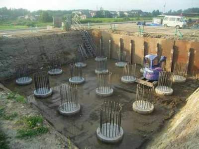
A column is placed at the center of the plate. The load is transferred to the plate through the centrally placed column.
The load can be transferred to the column either by gravity loading method or by truss method. Figure: Test Setup for Plate Load Test
For gravity loading method a platform is constructed over the column and load is applied to the platform by means of sandbags or any other dead loads. The hydraulic jack is placed in between column and loading platform for the application of gradual loading. This type of loading is called reaction loading.
At least two dial gauges should be placed at diagonal corners of the plate to record the settlement. The gauges are placed on a platform so that it does not settle with the plate.
Apply seating load of .7 T/m2 and release before the actual loading starts.
The initial readings are noted.
The load is then applied through the hydraulic jack and increased gradually. The increment is generally one-fifth of the expected safe bearing capacity or one-tenth of the ultimate bearing capacity or any other smaller value. The applied load is noted from the pressure gauge.
The settlement is observed for each increment and from dial gauge. After increasing the load-settlement should be observed after 1, 4, 10, 20, 40, and 60 minutes and then at hourly intervals until the rate of settlement is less than .02 mm per hour. The readings are noted in tabular form.
After completing the collection of data for a particular loading, the next load increment is applied and readings are noted under new load. This increment and data collection is repeated until the maximum load is applied. The maximum load is generally 1.5 times the expected ultimate load or 3 times of the expected allowable bearing pressure.{adselite}
Calculation of Bearing Capacity from Plate Load Test
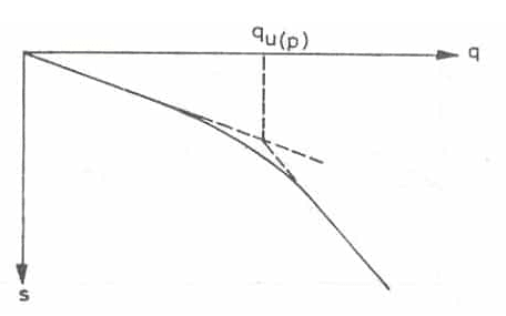
After the collection of field data, the load-settlement curve is drawn. It is a logarithmic graph where the load applied is plotted on X-axis and settlement on Y-axis. From the graph, the ultimate load for the plate is obtained which is the corresponding load for settlement of one-fifth of the plate width.
Figure: Load-settlement graph
When the points are plotted on the graph, the curve is broken at one point. The corresponding load to that breakpoint is considered to be the ultimate load on the plate. The ultimate bearing capacity can be calculated from the ultimate load from the plate. The ultimate bearing capacity is then divided by a suitable factor of safety to determine the safe bearing capacity of soil from the foundation.
General Equations for Calculation of Bearing Capacity of Soil
Soil Bearing Capacity Calculation for Clayey Soil
Following is the equation to determine soil bearing capacity for clay from the plate load test.
Ultimate Bearing Capacity = Ultimate Load for the Plate.
Soil Bearing Capacity Calculation for Sandy Soil
The followings are the equation to determine soil bearing capacity for sand from the plate load test.
The behavior of fine-grained cohesive soil depends on its mineral composition, water content, degree of saturation, and structure. In particular, the water content has always been considered an important and reliable indication of the behavior of cohesive soils since the beginning of soil mechanics. Swedish soil scientist and chemist Albert Mauritz Atterberg, in the early 1900s, first identified that a gradual decrease in water content of a clay soil slurry causes the soil to pass through different states or conditions. Atterberg Limit is a measure of the critical water content in a fine-grained soil.
Atterberg Limits and Indices
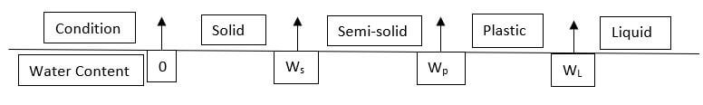
Atterberg defined the boundaries of four states of soil in the terms of “limits”. A fine-grained soil exists in different states depending on the amount of water in the soil system. The water content at which the soils change from one state to the other is known as consistency limits or Atterberg limit.
So the states are :
The liquid state is the state of a fine-grained soil at which the soil will flow on its own weight.
The plastic state is the condition at which the soil can be remolded to any shape without any development or cracks.
Semi-solid is the state at which the soil can remold but only with the development of cracks.
In the solid-state, the soil cannot be remolded at all, if done the soil specimen would get broken.
Atterberg also identified three limiting water contents, in between the soil states, that are commonly known as Atterberg’s limits. However, their potential use in soil mechanics was first indicated by Terzaghi. The upper and lower limits of water content within which a clay element exhibits a plastic behavior is defined as liquid and plastic limits respectively. Similarly, the limiting water content between semi-solid and solid states is the shrinkage limit
Liquid Limit
The liquid limit is the water content at the transition of liquid state to a plastic state, whereby it gains a certain small shearing strength. It is the minimum water content at which the soil is at the liquid state or the maximum water content at which the soil is in a plastic state. It is otherwise known as the minimum water content at which the soil tends to flow.
There are three methods of determining liquid limit:
The plastic limit is the minimum moisture content at which the soil can be deformed plastically. As standardized, it can be taken as the smallest water content at which the soil begins to crumble when rolled out into thin threads, approximately 3mm in diameter. That is at the plastic limit the soil must gain some minimum stiffness or strength.
Shrinkage Limit:
The shrinkage limit is the smallest water content below which a soil sample will not reduce its volume any, that is, it will not shrink any further with further drying. It is the maximum water content below which there is no volume change when the soil is dried. It is the minimum water content at which the soil can be saturated.
Importance of Atterberg Limits:
It has been found that both the liquid and plastic limit depends upon the type and amount of clay in a soil. However, the plasticity index depends mainly on the amount of clay. Thus, the plasticity index of a soil is a measure of the amount of clay in the soil.
As the particle size decreases, both the liquid and plastic limits increase, but the liquid limit increases at a greater rate. Therefore, the plasticity index increases at a rapid rate. When some silts are added to clay, it becomes leaner. It’s the liquid limit and plastic limit both decreases, but the former at a faster rate. The net effect is that the plasticity index decreases. Plasticity index, therefore, measures of the fineness of the particles.
The study of the plasticity index, in combination with liquid limit, gives information about the type of clay. Plasticity Chart, which is a plot between the plasticity index and liquid limit, is extremely useful for classification of fine-grained soils. In fact, the main use of these limits is in the classification of soils.
Sand Soils change from the liquid state to the semi-solid state rather abruptly. These soils do not possess plasticity and are classified as non-plastic. Soils with the liquid limit less than 20% are generally classified as sands
The plastic limit of soil increases if organic matter is added, without any significant increase in the liquid limit. Therefore soils with high organic content have a low plasticity index
The liquid limit of a soil is an indicator of the compressibility of a soil. The compressibility of the soil generally increases with an increase in liquid limit
The shrinkage index is directly proportional to the percentage of clay-size fraction present in the soil. It can be used as an indicator of clay.
The toughness index is a measure of the shearing strength of the soil at the plastic limit. A high value of toughness index indicates a high percentage of colloidal clay containing mineral montmorillonite.
When comparing the properties of two soils with equal values of the plasticity index, it is found that as the liquid limit increases, the dry strength and toughness decreases, whereas compressibility and permeability increases.
When comparing the properties of two soils with equal liquid limits, it is found that as the plasticity index increase, the dry strength and toughness increase, whereas the permeability decrease. However, the compressibility remains almost the same.
Please note that the information in Civiltoday.com is designed to provide general information on the topics presented. The information provided should not be used as a substitute for professional services.