Plate load test is a field test, which is performed to determine the ultimate bearing capacity of soil and the probable settlement under a given load. This test is very popular for selection and design of shallow foundation.
Advantages of Plate Load Test
The advantages of Plate Load Test are discussed below-
Being able to understand the foundation behavior under loading conditions.
Evaluation of bearing capacity of soil at a certain depth and prediction of settlement for a certain load.
Shallow foundation can be calculated considering the allowable bearing capacity, which can be predicted from the plate load test.
Time and cost-efficient.
Easy to perform.
Reliable.
Limitations of Plate Load Test
For gathering the necessary information regarding the design of a shallow foundation, the plate load test is very useful, but it has the following limitations.
The test predicts the behavior of soil located at a depth less than twice the depth of the width of the bearing plate. But in practical condition, the influence zone of a foundation is up to a much greater depth.
The plate load test is performed for a short time period, so it cannot predict the settlement for a longer period, especially for cohesive soil.
The bearing capacity for clayey soil is almost similar to the bearing capacity obtained from the plate load test, but in the case of dense sandy soil, the plate load test provides a conservative value. The actual capacity obtained for dense sandy soil is higher than the results from the plate load test.
The settlement for losing sandy soil is usually greater than the settlement indicated by the plate bearing test.
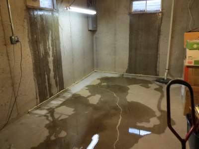
A building, which has a basement, has a great chance to face the problem of seepage of water or penetration of water through the wall of the basement especially at the time of heavy precipitation. This water from seepage stay at the floor line of a basement and if not controlled this condition can cause severe damage to the interior wall of the basement and the contents of the basement. This type of water seepage can get into the basement through the crack of the foundation walls and can develop over time if not it handled properly.
Porous building materials, such as concrete block, are capable of percolation and seepage of water through the building material itself and into the interior portion of the structure. Another source of moisture arises from capillary action and water vapor.
Facts and Ways of Water Intrusion into the Basement [3]:
Water can enter a basement in several ways. The conventional basement consists of three elements. Such as
A foundation wall.
A footer on which the wall rests.
A floor slab.
Underground water and Groundwater is the main source of water which will enter a basement.
If the water table rises above the level of the basement floor water can enter the basement through the side wall.
So what is the solution to this problem?????????????? The answer is basement waterproofing. Below we have discussed briefly the basement waterproofing, methods, which methods are efficient etc.
What is Basement Waterproofing?
Basement waterproofing means the technique and the materials to prevent seepage of water into the basement or the penetration of water into the basement of a house or structure. This waterproofing is for an underground room of a structure.
Method of Basement Waterproofing
There have many ways of solving the problem of seepage of water but all the way is not truly efficient because of cost and difficulty of installation.
Some Method and the fact about those methods [2]:
Trying to seal the crack after the formation of a crack of a foundation wall. It can be done at inside or outside. It is not only costly but also ineffective.
Moisture resistant flashings or coatings can be a solution but Moisture-resistant flashings or coatings tend to fracture and tear due to building expansion, settling, and careless installation.
By setting a plywood board against the foundation wall before the pouring of concrete slab water can be drained from the interior of the basement. Then the board is removed while the concrete is still "green' and not completely set. But this procedure has some disadvantages:
it causes damage to the edge of the concrete floor;
it results in additional labor costs,
it may cause the concrete floor to shift.
So an efficient method is highly desirable for waterproofing solution. Two methods, which are considered as efficient, are described below.
Efficient Methods of Basement Waterproofing
Method 1[2]
Apparatus: Drainage Control Apparatus
Part of the Apparatus: Vertical leg, Horizontal leg, Embossments, Longitudinal spacer slip, Drainpipe.
Methodology: A drainage control apparatus has been used in this method. A vertical leg of this apparatus has been set up to the vertical side wall of the basement and a horizontal leg has been set up to the top of the foundation footing. The vertical leg consists of an embossment at the bottom end of the vertical leg. The vertical leg also consists of a longitudinal spacer lip at the upper end of the vertical leg. Both the embossment and the spacer lip touch vertical side wall of the basement to maintain a gap between the vertical leg and the vertical side wall. The horizontal leg consists of channels to flow water into a drain pipe. For the corner of the basement, the apparatus is named as corner drainage control apparatus but the setting of the apparatus is same. After that concrete is poured to fulfill the slab and then the vertical portion of the apparatus has been cut off to level the apparatus with slab end. This invention is quite easy to install and it is also advantageous because it can drain water from the interior of the basement.
Method 2[1]
A sump system in geometry is rectangular. It has two side elements with apertures to exchange the groundwater while blocking debris. In another side element, an adjustable inlet had been provided to connect other elements of a basement waterproofing system to the sump liner. After that in the sump liner, a base configured can be used to provide a built-in stand for the sump pump. The pump stand contains a lip including notches to allow the fallen of debris and collection in a trough around the periphery of the base. The base further provides an underside cavity which accommodates an obstruction in the floor of the sum hole. A removable lid used to facilitate the access of the interior of the sump liner and also contains a breakaway feature to accommodate discharge piping. The sump liner can be oriented into the sump hole to protect the basement foundation from the adverse effect of erosion.
References
Andras, S. Basement sump system, and method. U.S. Patent 8973324B2 filed January 24, 2013, and issued March 10, 2015.
Geske, D. R. Apparatus, and method for waterproofing basements. U.S. Patent 4869032A filed September 25, 1987, and issued September 26, 1989.
Read, R. R. Basement Waterproofing. U.S. Patent 5845456A filed December 14, 1990, and issued December 8, 1998.
DiFiore, D. Basement waterproofing system. U.S. Patent 4136500A filed March 30, 1978, and issued January 30, 1979.
Footing and foundation are known as selfsame. People are confused if there is an identical difference. However, there are few major differences between footing and foundation. They are discussed below.
Footing vs Foundation
Followings are the differences between Footing and Foundation:
Footing
Foundation
1
The footing is a formation which is in contact with the ground.
Foundation is a structure which transfers its gravity loads to earth from superstructure.
2
Footing can be analogized with the feet of the leg.
A foundation that consists of one, two, or more tiers of beams (typically steel) superimposed on a layer of concrete to disperse load over an extensive area is a grillage foundation. It is used at the base of columns. These tiers are encased in concrete and are at right angles to each other. This type of foundation is generally used for heavy structure columns piers and scaffolds.
Though both foundation and grillage look the same they are different. Where the foundation transfers load from the structure to the ground, grillage disperses heavy loads over large areas.
Types of Grillage Foundation
According to the materials used in construction, Grillage foundation is of two types:
Steel Grillage foundation
Timber Grillage Foundation
Steel Grillage Foundation
Steel Grillage foundation consists of steel joints or beams which are provided in single or double tiers. Its name defines its function and structure as it is made up of steel beams, structurally known as rolled steel joists. A minimum cover of 10 cm is kept on the outer sides of the external beams as well as above the upper flanges of the top tier. The depth of concrete should be at least 15 cm. After we level the base and pour the concrete, we should check if the compaction is done properly and formed an impervious layer of a thickness not less than 15 cm. It shields steel joists from groundwater, which can lead to corrosion. Then we lay the first layer of beams over the concrete bed at a distance of 100mm to 300mm, with the help of pipe separators. Next, we pour concrete between and around the beams of the first tier. After that, we place the second tier of the beam at the right angle to the first tiers with the help of the separator. Then again, we pour concrete between and around the steel beams. By doing so, we connect the steel stanchions to the upper tier with the help of a base plate, side angles, and a gusset plate. These connecting elements are also embedded in the concrete to make the joint rigid.
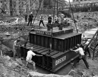
Construction of the World Trade Center Grillage Foundation.Picture reference: raredelights.com
Timber Grillage Foundation
Timber type foundation is provided for heavily loaded masonry walls of timber columns. This foundation is especially useful in waterlogged areas, where the bearing capacity of the soil is very low and where the loading on the soil is limited to 50-60 KN/m2. Timber planks and timber beams are used instead of steel joists. there is no concrete surrounded between the timber joints. However, the bottom concrete provided in steel grillage is replaced by a timber platform constructed of timber planks. The excavation of the base is leveled. The bottom layer of timber planks of size 20-30cm, width 5-7.5cm thick is laid side by side without any gap between them. Over the top of this layer, a timber beam of the same section as that of the wooden post is placed at right angles. Then another layer of planks again is laid at right angles to the direction of beams. The upper layer of planks maybe 7.5-10 cm. Thick, extending over the full width of the wall base, over which masonry wall is constructed.
Design of Grillage Foundation
For the design of grillage foundation, it is required to calculate the loads and moments from the superstructure. From this, we have to determine the required base area for a suitable allowable ground bearing pressure of the condition. Dividing this area, we will find out the numbers and size of each grillage layer. Then, we have to design the layer so that it cantilevers from the edge of the layer above. It will determine the beam sizes required to resist the bending moments and shear forces. The grillage cannot be enclosed in concrete and the order, because then the composite action of the beam and concrete will be demoralized. The method of construction and loading should be compatible with the design necessities
Installation of Grillage Foundation
Followings are the steps of grillage foundation installation:
First, for solid monolithic grillage, we have to produce and install the framework. We prefer this grillage because it is more dependable.
Formwork is made from edging boards in the form of rectangular troughs. Its height is 1 ft and width are equal to the minimum wall thickness of the house. It must be set about 6-8 inches gap in between each grillage.
Inside the formwork, we have to set a framework of reinforcements connections using binding wire. The least distance from the frame to the side of the formwork is required to be same.
Next, the reinforcement is linked with the same binding wire used before.
Then, Concrete has to be prepared using the cement mixer. It is poured in the formwork in a continuous cycle. Fittings must be placed on a height about 25-30mm so that it completely immerses in concrete. Concrete should be carefully poured to avoid unwanted cavities. 6. After filling the surface, the surface has to be leveled and left to dry. When it is dried, the formwork can be removed. The foundation is ready now.
If you're looking for information on helical piers, you've come to the right place. Helical piers are a common type of foundationpier used in both residential and commercial construction. Please note that there is no difference between helical piers and helical pile foundations. Both terms refer to steel shafts with helical blades that are driven into the ground to provide support for structures.
In this article, we'll cover everything you need to know about helical pier foundations, including what are helical piers. how they work, and their many benefits.
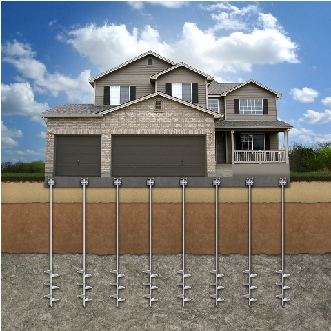
What are Helical Piers?
Helical piers are foundation support systems that consist of steel shafts with helically-shaped blades. These piers are driven into the ground using hydraulic equipment, and they can be used to support both new construction and existing structures.
They are most commonly used in situations where the soil is too weak or unstable to support traditional foundation methods such as driven piles or drilled shafts. Helical piles are also used in areas where there is limited space for equipment, making them ideal for tight urban sites.
The helical piers come in a variety of sizes, depending on the application. The most common sizes are 3/8 inch, 1/2 inch, and 5/8 inch. The piers are also available in a variety of weights, depending on the application. The most common weights are 30, 60, and 90 pounds.
Helical piers work by transferring a load of a structure from unstable or poor soil to more stable soil or bedrock. The helically-shaped blades on the pier act as screws, providing a secure connection between the pier and the ground. The pier is then connected to the structure, allowing the load to be transferred to the pier and away from the unstable soil. This can provide a more stable foundation for the structure and can help to prevent foundation settlement and other damage.
How to Install Helical Piers?
Followings are the stages followed during helical pier installation:
Excavation
The dig site is excavated to the specified depth using a variety of equipment. The excavation is then backfilled with gravel to improve the stability of the pier.
Drilling
A hollow drill bit is used to bore a hole through the soil and into the bedrock or stable soil below.
Insertion
The pier is inserted into the drilled hole and secured in place.
Grouting
A grout mixture is injected into the space around the pier to further secure it in place and to fill any voids.
Testing
The pier is tested to ensure that it can support the loads that will be placed on it.
Backfill
The excavation is backfilled with soil and compacted to finish the installation.
When Should Helical Pier Foundation be Used?
Helical piers should be used when you need a quick, easy, and versatile solution for foundation support. They can be used in a variety of applications, including new construction, repairs, and retrofits. Helical piers are also less expensive than other foundation support systems, making them a great option for budget-conscious homeowners.
Residential applications for helical piles include new home construction, additions, decks, porches, and garages. They can also be used to support light poles, basketball goals, and other outdoor structures.
Commercial applications include office buildings, shopping centers, and industrial parks. Helical piles are also commonly used to support cell phone towers and wind turbines.
Advantages of Helical Piers
There are many advantages and benefits to using helical piers.
Small disturbance: The helical piers screw into the ground, causing a minimal ground disturbance.
Quick installation: The helical piers are installed quickly and efficiently, oftentimes in less than a day.
Easy access: The helical piers are installed from the exterior of a building, meaning that there is no need to move equipment around the inside of a structure.
Cost-effective: The helical piers are a cost-effective way to stabilize a structure.
No heavy equipment needed: The helical piers are installed using a hand-held power drill.
Flexibility: The helical piers can be used to stabilize structures that have already been built or to stabilize structures that are being built.
Versatility: The helical piers can be used to stabilize a wide variety of structures.
Environmentally friendly: The helical piers are made from recycled steel and are completely non-toxic.
Ability to be removed: The helical piers can be removed if necessary.
Limitations of Helical Piles
There are some limitations to using helical piers.
The load-bearing capacity of helical piles is limited by the torque that can be applied to the shaft during installation.
The depth to which helical piles can be installed is limited by the length of the shaft.
Helical piles are not suitable for very soft or loose soils.
If you're in need of foundation support, helical piers may be the perfect solution for you. Contact a local foundation expert to learn more about this innovative foundation support system. If you really get impressed regarding helical piers call helical pier contractors near you to do this job.
Please note that the information in Civiltoday.com is designed to provide general information on the topics presented. The information provided should not be used as a substitute for professional services.