Arthur Casagrande developed a standard device for the determination of liquid limit suggesting that at the water content of liquid limit a clay soil has a shear strength of approximately 2.5 kPa. The device consists of a metal cup seated onto a hard rubber base and fixed to a crankshaft arrangement with a handle so that the cup can be alternately raised and dropped.
The soil is first dried sufficiently to be broken up by a mortar and pestle.
It is then sieved using a 425-micrometer sieve and materials passing are taken for the limit tests.
The soil sample is mixed thoroughly with water into a smooth thick paste, and stored in an airtight container for 24 hours to allow the water to mix thoroughly with all the soil grains.
At the time of testing, the soil is remixed and a portion of it placed in the metal cup. The soil paste is leveled off in the cup to give a maximum depth of 8mm.
A groove is formed in the soil along the midsection of the cup, using a standard grooving tool.
The handle is turned at two revolutions per seconds and the number of blows is counted until the two parts of the soil come in continuous contact at the bottom of the groove along about 12mm.
A sample is taken from the closed portion of the groove for moisture content determination.
The remaining soil is removed from the cup to mix with the original paste adding further water, and the test is repeated for several times.
The number of blows and moisture content in each trial are recorded. It is desirable to have the tests in the blow range of 15 to 35. The liquid limit according to this method, is defined as the moisture content at which 25 blows are required to close the groove.
A semi-log plot of the points is obtained with a number of blows as abscissa in logarithmic scale as against moisture content in linear scale. A best-fitting straight line is drawn which is termed as flow curve. The moisture content corresponding to 25 blows is read from the flow curve as the liquid limit of soil.
California bearing ratio test is one of the soil strength evaluation tests. In this test, the relative strength of a soil specimen is measured with respect to the standard sample.
In this article, the definition of the California bearing ratio is provided. Also, the required apparatus of the CBR test of soil, full test procedure, the calculation to evaluate California Bearing Ratio, and uses of the test result are explained here.
What is the California Bearing Ratio of Soil?
California bearing ratio is the percentage of stress a soil specimen can resist for a certain amount of penetration relative to the value of stress of which a standard soil could resist. Basically, the value is an indicator of the strength of the soil.
\[CBR=\frac{P_{s}}{P_{std.}} \times100 \%\]
\[{P_{s}}= Stress \; carried \; by \; site\;soil\cdot\]
\[{P_{std.}}= Stress \; carried \; by \; standard \;soil\cdot\]
California Bearing Ratio Test of Soil
California bearing ratio test is basically a load test that is performed on the soil surface to determine its CBR value.
In summary,
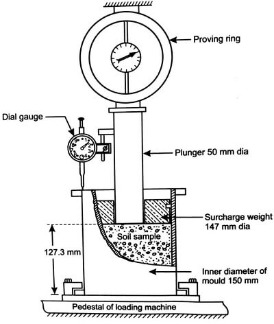
A mold is filled with the soil specimen. It is compacted into the mold with a rammer. Then the mold is soaked in water for a certain period of time. Then a loading machine is used to apply load on a plunger. This will penetrate through the soil mold. The machine will penetrate through the soil by increasing the load gradually. There are one proving ring and one dial gauge attached to the machine. The dial gauge indicates the penetration amount. The proving ring indicates the amount of load machine is applying to the surface. For certain amounts of penetrations, corresponding load values have to be recorded. Later stress vs. penetration curve is drawn by using these values. From that curve, both for 1 in (2.54 mm) & 2 in (5.08 mm) penetration, corresponding stress value is determined. These values are used in the equation mentioned above to calculate the CBR value.
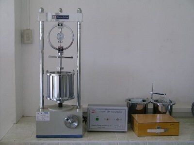
Laboratory California Bearing Ratio Test Apparatus
The followings are the apparatus required to perform the CBR test of soil.
Loading Machine
Penetration Piston
Sieves
Mold
Spacer Disk
Mixing Tools
Details of this equipment are given below.
Loading Machine
with a capability of moving rate 0.05 in. (1.27 mm)/min to apply compressive force in the piston. A penetration measuring device (dial indicator) has to be attached to the machine to provide accurate penetration measurements.
Penetration Piston
A metal piston with 1.954 ± 0.005 in. (49.63 ± 0.13 mm) in diameter and not less than 4 in. (101.6 mm) long.
Sieves
Two sieves are required. ¾ in. (19 mm) & #4 (4.75 mm).
Mold
a rigid metal cylinder with an inside diameter of 6 ± 0.026 inch (152.4 ± 0.66 mm) and a height of 7 ± 0.018 inches (177.8 ± 0.46 mm). It shall be provided with a metal extension collar at least 2.0 inches (50.8 mm) in height.
Spacer Disk
A circular metal spacer disc (see Figure 16.1) having a minimum outside diameter of 5 15/16 inches (150.8 mm). The spacer disc shall be 2.416 ± 0.005 inches (61.37 ± 0.127 mm) in height.
Misc. Mixing Tools
mixing pan, spoon, trowel, spatual, etc.
Rammer for compaction, Balance, Filter Paper, Drying oven, Soaking Tank.
CBR Test Procedure
Detail CBR test procedure is described below.
Specimen Preparation
A ¾ in (19 mm) sieve is used to sieve the soil specimen. If all material passes through the sieve, we can use all of it for the test. But some of the material might be retained in the sieve. In that situation have to replace the retained amount with an equal amount of the materials which pass ¾ in the sieve and retained on the #4 sieve.
After sieving, make 3 sample specimens each containing 6.8 kg (15 lb).
Specimen 1,2,3 will be compacted with about 10, 30 & 56 blows respectively. This will provide variations in the percentage of maximum dry density.
Sufficient amounts of water shall be mixed with specimens to maintain optimum water content.
The mold shall be attached to the base plate with the extension collar. Then the weight shall be measured. Then a spacer disk shall be placed into the mold with a filter paper on top of the spacer disk.
The mold shall be filled with soil in 3 layers. For example: for specimen 1, we have to provide 10 blows per layer with the rammer for the compaction. The water content of the material shall be determined before and after the compaction procedure.
Then the extension collar shall be removed and the top of the mold shall be trimmed with a straightedge to smoothen the surface.
The other two specimens shall be compacted following the same procedures mentioned above.
Remove spacer disk, base plate. then the weight of Mold plus compacted soil shall be measured.
Then invert the mold and soil and attach the base plate to the mold with a coarse filter paper.
Soaking
Place a specified amount of surcharge weight (typically 4.54 kg) on top of the base plate.
Use a water tank to soak the specimen for around 4 days (96 hrs.)
Measure the height of the specimen before and after soaking to determine the swell percentage of the initial height. An expansion measurement equipment can be used for this purpose.
After 4 days of soaking, the mold shall be from water. The base plate, filter paper, and surcharge weights shall also be removed. mass of the mold plus soil shall be measured.
Load Test
Place the mold under the penetration piston of the compressing machine. The same amount of surcharge weight (4.54 kg) shall be placed on top of the mold.
Then the compressing machine shall be started to apply load with a constant penetration rate of 0.05 in. (1.27 mm)/min. The piston will start to penetrate through the soil for the loading.
The machine has two indicators. One is a proving ring and another is dial gauge. The dial gauge indicates the penetration and the proving ring will indicate the amount of load is applied to gain that penetration.
See the table below, column 2 shall be filled in with corresponding proving ring readings for the penetrations specified in column 1.
Proving readings shall be multiplied with machine constant to find the piston load (col. 3)
Then penetration stress shall be determined from piston load (col. 4)
Penetration (in)
Proving Ring (Dial Reading)
Piston Load (lb)
Penetration Stress (psi)
0
0.025
0.05
0.075
0.1
0.125
0.150
0.175
0.2
0.3
0.4
0.5
California Bearing Ratio Calculation from the Test Values
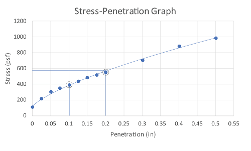
Stress-Strain Curve
Then Stress vs. Penetration (strain) curve shall be drawn. If the curve is concave upward in the near of the origin, the values have to be adjusted according to the guidelines.
CBR Calculation
From the curve, corresponding stress shall be determined for 0.1 in. (2.55 mm) & 0.2 in (5.08 mm) penetration. See the figure.
Use the equation to determine the CBR value \[CBR_{\;0.1 in}=\frac{Stress\;of \;soil \;specimen \;for \;0.1 \;in penetration}{1000 \; psi}\times100\] \[CBR_{\;0.2 in}=\frac{Stress\;of \;soil \;specimen \;for \;0.2 \;in penetration}{1500 \; psi}\times100\]
Generally, CBR0.1 is taken as a CBR value. But for the condition where, CBR0.1 in < CBR0.2 in significantly, the test shall be done again from the beginning.
CBR of each specimen shall be determined in this process.
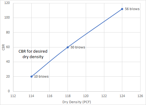
Design Bearing Ratio for Specified Dry Density
The dry density of each specimen (10, 30 & 56 blows) shall be calculated. Then a graph shall be drawn with dry density vs. corresponding CBR values of each specimen. (see the figure). The curve shall be used to determine the CBR value for specified dry density.
CBR test pdf
To ease your study easy a pdf version of this article is provided here. Click to below the download link for the CBR test pdf.
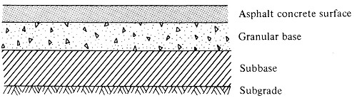
In flexible pavements, different kinds of layers are used to withstand the traffic load. CBR value is required to determine the thickness of those layers, especially for base and subgrade materials.
For lower CBR, the thickness of layers will be higher and vice versa.
If the CBR value of a material is too low, the layer thickness will be much higher. It would not be cost-effective to work with that material.
The Standard Penetration Test, also known as SPT, is an is-situ test of soil to evaluate the soil properties. Around the world, it is the most popular test of soil for subsurface exploration. The measure of soil penetration resistance and collected soil sample is used for foundation design.
The popularity of SPT is mainly due to the advantages it provides. In this article, we will unfold these advantages along with Standard Penetration Test disadvantages for you.
Advantages of Standard Penetration Test (SPT)
The followings are the major advantages of the Standard Penetration Test.
It is an inexpensive test.
The test can be done quickly.
The test procedure is relatively simple to perform.
Collected soil samples can be used for soil type identification.
The compressibility and relative strength index of the soil can be established form SPT data.
Able to penetrate dense layers, gravel, and tilt.
With SPT-N values, the method based on this history can reflect actual soil behavior during earthquakes, which cannot be simulated in a lab.
{adselite}
Disadvantages of Standard Penetration Test (SPT)
The followings are the disadvantages or limitations of the Standard Penetration Test.
The type of soils impacts the usefulness of the obtained result. Most useful results can be achieved in fine-grained sands.
Non-disturbed samples cannot be collected. The samples are highly disturbed.
The test requires borehole preparation.
It is difficult to achieve a true result if a hard stone is encountered.
The test requires heavy equipment.
It is difficult to remove the sampler from the hard layer.
Please note that the information in Civiltoday.com is designed to provide general information on the topics presented. The information provided should not be used as a substitute for professional services.