


For designing shallow foundations, it is necessary to know the bearing capacity of soil at the desired depth. The plate load test is performed on-site to determine the ultimate bearing capacity of soil at the desired depth. Data from the plate load test is helpful to confirm the design assumptions made from soil tests or can be used as a design parameter.
Contents [show/hide]
What is the Plate Load Test?
The plate load test is a field test, which is performed to determine the ultimate bearing capacity of the soil and the probable settlement under a given load. This test is very popular for the selection and design of the shallow foundation.
For performing this test, the plate is placed at the desired depth, then the load is applied gradually and the settlement for each increment of the load is recorded. At one point a settlement occurs at a rapid rate, the total load up to that point is calculated and divided by the area of the plate to determine the ultimate bearing capacity of soil at that depth. The ultimate bearing capacity is then divided by a safety factor (typically 2.5~3) to determine the safe bearing capacity.
Plate Load Test Apparatus / Equipment
The following plate load test apparatus is necessary for performing the test.
- A steel plate is at least 300 mm square and 6 mm thick.
- Hydraulic jack & pump
- A hydraulic jack with a capacity of at least 1.5 times the anticipated test load.
- A set of steel shims, at least 6 mm thick.
- Reaction beam or reaction truss
- A dial gauge, with a range of 0-250 mm and an accuracy of 0.02 mm.
- Pressure gauge
- A loading frame with a capacity of at least 1.5 times the anticipated test load. The frame should be designed so that it can be firmly attached to the ground, and so that the load can be applied to the center of the plate.
- Necessary equipment for the loading platform.
- A steel rule or tape measure is at least 3 m long.
- Tripod, Plumb bob, spirit level, etc.
- A hammer.
- A set of wrenches.
- A clean, dry cloth.
Plate Load Test Procedure
The necessary steps to perform a plate load test is written below-
- Excavate test pit up to the desired depth. The pit size should be at least 5 times the size of the test plate (Bp).
- At the center of the pit, a small hole or depression is created. The size of the hole is the same as the size of the steel plate. The bottom level of the hole should correspond to the level of the actual foundation. The depth of the hole is created such that the ratio of the depth to width of the hole is equal to the ratio of the actual depth to the actual width of the foundation.
- A mild steel plate is used as a load-bearing plate whose thickness should be at least 25 mm thickness and size may vary from 300 mm to 750 mm. The plate can be square or circular. Generally, a square plate is used for square footing and a circular plate is used for circular footing.
- A column is placed at the center of the plate. The load is transferred to the plate through the centrally placed column.
- The load can be transferred to the column either by gravity loading method or by truss method.

Figure: Test Setup for Plate Load Test - For gravity loading method a platform is constructed over the column and load is applied to the platform by means of sandbags or any other dead loads. The hydraulic jack is placed in between column and loading platform for the application of gradual loading. This type of loading is called reaction loading.
- At least two dial gauges should be placed at diagonal corners of the plate to record the settlement. The gauges are placed on a platform so that it does not settle with the plate.
- Apply seating load of .7 T/m2 and release before the actual loading starts.
- The initial readings are noted.
- The load is then applied through the hydraulic jack and increased gradually. The increment is generally one-fifth of the expected safe bearing capacity or one-tenth of the ultimate bearing capacity or any other smaller value. The applied load is noted from the pressure gauge.
- The settlement is observed for each increment and from dial gauge. After increasing the load-settlement should be observed after 1, 4, 10, 20, 40, and 60 minutes and then at hourly intervals until the rate of settlement is less than .02 mm per hour. The readings are noted in tabular form.
- After completing the collection of data for a particular loading, the next load increment is applied and readings are noted under new load. This increment and data collection is repeated until the maximum load is applied. The maximum load is generally 1.5 times the expected ultimate load or 3 times of the expected allowable bearing pressure.{adselite}
Calculation of Bearing Capacity from Plate Load Test
After the collection of field data, the load-settlement curve is drawn. It is a logarithmic graph where the load applied is plotted on X-axis and settlement on Y-axis. From the graph, the ultimate load for the plate is obtained which is the corresponding load for settlement of one-fifth of the plate width.
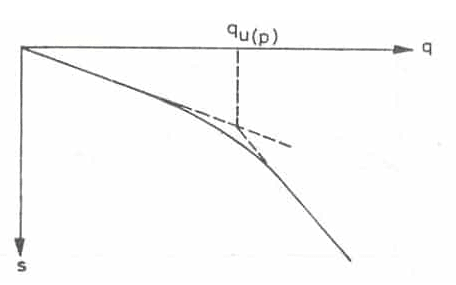
When the points are plotted on the graph, the curve is broken at one point. The corresponding load to that breakpoint is considered to be the ultimate load on the plate. The ultimate bearing capacity can be calculated from the ultimate load from the plate. The ultimate bearing capacity is then divided by a suitable factor of safety to determine the safe bearing capacity of soil from the foundation.
General Equations for Calculation of Bearing Capacity of Soil
Soil Bearing Capacity Calculation for Clayey Soil
Following is the equation to determine soil bearing capacity for clay from the plate load test.
Ultimate Bearing Capacity = Ultimate Load for the Plate.
Soil Bearing Capacity Calculation for Sandy Soil
The followings are the equation to determine soil bearing capacity for sand from the plate load test.
\[Ultimate\;bearing\;capacity =Ultimate \;load \;for \;plate \times \frac{Width \;of \;Pit}{Size \;of \;Plate}\]
\[Safe\;bearing\;capacity = \frac{Ultimate\;Bearing \;Capacity}{Factor\;of\;Safety}\]
Typically, the range for the factor of safety varies from 2 to 3.
Equations for Foundation Settlement Calculation from Plate Load Test
The following equations can be used for foundation settlement calculation.
Foundation Settlement Calculation for Clayey Soil
Following is the equation to determine foundation settlement for clay from the plate load test.
\[Settlement\;of\;the\;foundation =Settlement\;of\;plate \times \frac{Width \;of \;Pit}{Size \;of \;Plate}\]
Foundation Settlement Calculation for Sandy Soil
Following is the equation to determine foundation settlement for sand from the plate load test.
\[Settlement\;of\;the\;foundation = Settlement\;of\;plate \times \frac{Width\;of\;Pit \times(Size\;of\;Plate+0.3)}{Size\;of\;Plate\times(Width\;of\;Pit+0.3)^{2}}\]
Plate Load Test Limitations & Advantages
Please read the following article to learn all the plate load test limitations & plate load test advantages.